A magnetic dipole can be made by running a current through a loop of wire. Most permanent magnets are bar magnets, however, and these are still commonly referred to as producing a dipole field. In this topic we will examine a very simple case in which the magnetization of a cylinder is used to determine (and illustrate) the resulting magnetic field.
Consider here a cylinder of length, L, and radius, R, where the ratio of these values will be set at three different values. We have a short and fat cylinder in which L << R, a long and skinny cylinder in which L >> R, and a nearly cubic cylinder in which L ≈ R. Each of these cylinders features a magnetization, M, that is given by M = α z, where α is a constant. The unit vector z is parallel to L, the axial direction of the cylinder. We will quantitatively determine the magnetic field produced in each of these cases.
Figure 1 displays the geometry of this topic. The cylinder is shown to provide perspective for the different scales being considered.

When the magnetization of an object is given, one method that may be used to determine its magnetic field involves solving for its bound currents. The volume, Jb, and surface, Kb, bound currents are related to the magnetization by,
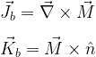
where n represents the vector normal to any surface of the cylinder (i.e. each individual surface of the cylinder has its own vector normal and therefore its own bound surface current).
The bound currents represent all of the current in this system∗. The bound volume current is solved for as (including the full cylindrical coordinates curl expression, which is always a helpful reference),

![= \left[ \frac{1}{r}\frac{\partial M_z}{\partial \phi} - \frac{\partial M_\phi}{\partial z} \right] \hat{r} + \left[\frac{\partial M_r}{\partial z} - \frac{\partial M_z}{\partial r}\right] \hat{\phi} + \left[\frac{1}{r}\frac{\partial}{\partial r}\left(rM_\phi \right) - \frac{1}{r}\frac{\partial M_r}{\partial \phi} \right]\hat{z} \\ \\ \\ = \left[ \frac{1}{r}\frac{\partial\alpha}{\partial \phi} - 0 \right]\hat{r} + \left[0 - \frac{\partial \alpha}{\partial r} \right]\hat{\phi} + [0-0]\hat{z} \\ \\ \\ = 0](https://s0.wp.com/latex.php?latex=%3D+%5Cleft%5B+%5Cfrac%7B1%7D%7Br%7D%5Cfrac%7B%5Cpartial+M_z%7D%7B%5Cpartial+%5Cphi%7D+-+%5Cfrac%7B%5Cpartial+M_%5Cphi%7D%7B%5Cpartial+z%7D+%5Cright%5D+%5Chat%7Br%7D+%2B+%5Cleft%5B%5Cfrac%7B%5Cpartial+M_r%7D%7B%5Cpartial+z%7D+-+%5Cfrac%7B%5Cpartial+M_z%7D%7B%5Cpartial+r%7D%5Cright%5D+%5Chat%7B%5Cphi%7D+%2B+%5Cleft%5B%5Cfrac%7B1%7D%7Br%7D%5Cfrac%7B%5Cpartial%7D%7B%5Cpartial+r%7D%5Cleft%28rM_%5Cphi+%5Cright%29+-+%5Cfrac%7B1%7D%7Br%7D%5Cfrac%7B%5Cpartial+M_r%7D%7B%5Cpartial+%5Cphi%7D+%5Cright%5D%5Chat%7Bz%7D+%5C%5C+%5C%5C+%5C%5C++%3D+%5Cleft%5B+%5Cfrac%7B1%7D%7Br%7D%5Cfrac%7B%5Cpartial%5Calpha%7D%7B%5Cpartial+%5Cphi%7D+-+0+%5Cright%5D%5Chat%7Br%7D+%2B+%5Cleft%5B0+-+%5Cfrac%7B%5Cpartial+%5Calpha%7D%7B%5Cpartial+r%7D+%5Cright%5D%5Chat%7B%5Cphi%7D+%2B+%5B0-0%5D%5Chat%7Bz%7D+%5C%5C+%5C%5C+%5C%5C++%3D+0&bg=ffffff&fg=000&s=2&c=20201002)
and the conceptual way to understand this zero result is that a constant field has no curl.
Bound surface currents may exist on the cylindrical surface and also on either circular face. For the cylindrical surface we have,

and the Φ direction correctly describes the cylindrical surface so this is a physically reasonable result.
Circular faces are found at z = ± L/2. The bound surface current at these faces is, first for z = +1/2,
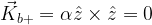
and then for z = -1/2,

and we now have all of the current in this system.
The only current is directed along +Φ and is found on the cylindrical surface. This is equivalent to a ring current, which would be a magnetic dipole. Using the right-hand rule we determine that the resultant magnetic field must be in the +z direction.
Figure 2 shows the basic result for this object. The current flows along the surface of the cylinder, resulting in a magnetic field that is directed along +z on the cylinder’s axis. This is similar to the current found in a solenoid, so if the cylinder is long then the magnetic field is constant inside.

The following are explanations for qualitatively describing the field that results from each case of specific cylinder scale.
Case of L << R

Case of L >> R

Case of L ≈ R

∗ Magnetic fields may also be produced by free currents. There are no free currents in this system. In a theoretical treatment such as this, any free current has to be placed there by the author (i.e. you cannot solve for free currents, they can only be given as part of the topic setup).
Leave a Reply